
← forward reverse interlock wiring diagram forward reverse wiring diagram dc motor →
PLC Implementation Of Forward/Reverse Motor Circuit With Interlocking. 8 Images about PLC Implementation Of Forward/Reverse Motor Circuit With Interlocking : PLC Implementation Of Forward/Reverse Motor Circuit With Interlocking, Auto star delta and forward reverse control circuit for motor and also 6 main control pcb comparison, Figure 3 f7 connection diagram | Yaskawa.
PLC Implementation Of Forward/Reverse Motor Circuit With Interlocking
 electrical-engineering-portal.com
motor circuit reverse forward plc interlocking electrical push implementation hardwired interlockings illustrates button figure
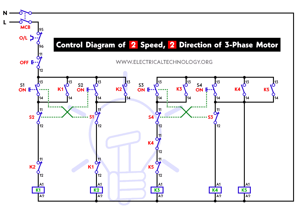
Two Speeds, Two Directions Multispeed 3-phase Motor Power & Control
 www.electricaltechnology.org
control motor phase diagram directions power speeds multispeed wiring circuit electrical diagrams technology
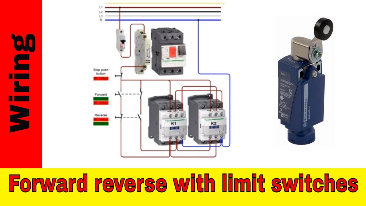
Forward Reverse Motor Control Wiring With Limit Switches. - YouTube
 www.youtube.com
limit motor reverse control forward wiring switches
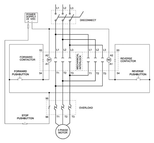
Wiring Diagram: Chapter 1.2. Full-voltage Reversing 3-phase Motors
 anywiringdiagram.blogspot.com
reversing contactor 230v automationdirect intended pertaining mühendisliği elektronik schaltplan inversión voltaje
Wireing A New Motor
 www.practicalmachinist.com
motor switch wiring diagram reversing techtop ac duty farm wireing wire t3 t4 t5 t8 t2 tom
Auto Star Delta And Forward Reverse Control Circuit For Motor
 electricallearn.com
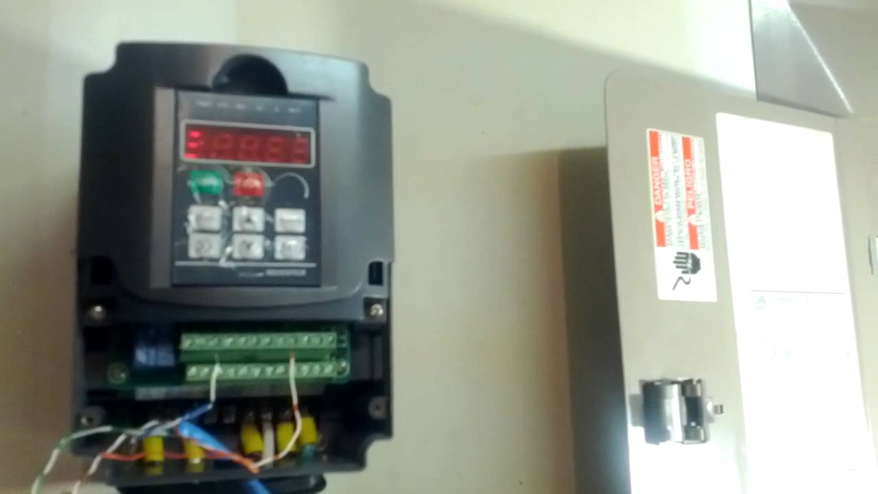
Remote Control On Vfd( First Test Of Remote Control Of Huanyang VFD And
 www.youtube.com
vfd huanyang remote control lathe zzo
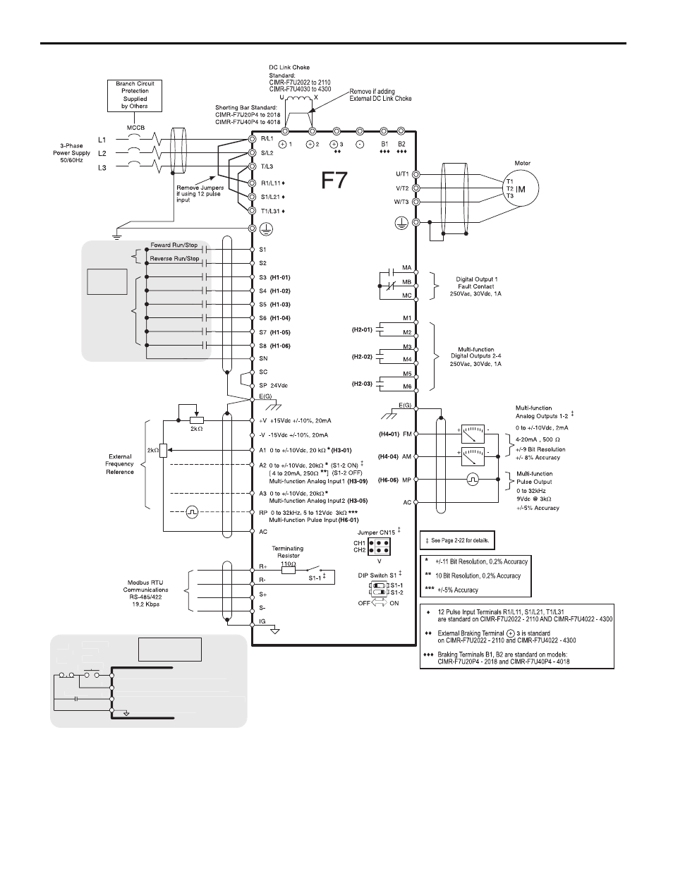
6 Main Control Pcb Comparison, Figure 3 F7 Connection Diagram | Yaskawa
 www.manualsdir.com
yaskawa diagram f7 pcb comparison control main a1000 connection manual user figure
Two speeds, two directions multispeed 3-phase motor power & control. 6 main control pcb comparison, figure 3 f7 connection diagram. Forward reverse motor control wiring with limit switches.